Friday, October 25, 2013

Process Optimization- Body

To begin the process optimization process, our team began by making the body.

For our first run, we utilized the default settings, but approximated the volume of the yoyo.

First body made! Looks really great, but unfortunately there was a lot of flashing
Second body! Still a lot of flashing... 
In order to reduce the flashing, we reduced the velocity at the end of the stroke. We got less flashing, which was great!
Third body! Even less flashing.
 To reduce flashing even more, especially since it appeared to only be on one side of the part, we shimmed the core with a single sheet of paper.
Flash is almost gone!
Shimming the core to prevent flashing

Eventually, we added 4 sheets of paper and were able to minimize the flash and get a great part!


The finalized parameters for the body

Monday, October 21, 2013

Manufactured Mold Designs

A quick look at our manufactured mold designs so far:


Body Cavity Mold
Hole in the center of the cavity mold will be used to suspend the nut for the shaft within the plastic
Body Core: Features 6 symmetric ejection holes, allowing for removal of the body from the core.

During machining, we had to make some changes to the part.
Due to the size of the body part, we ended up using a thicker (1.25") mold blank for the cavity at Dave's suggestion. Ideally, we would have used the thicker blank for the core as well, but Dave is sure either would work. Also, the runner on the cavity mold was originally 0.030" deep, but Dave suggested deepening it to 0.090" deep to allow the molten plastic to flow into the mold better.


Ring Cavity Molds
Design Features: 2 additional runners added around the mold, create fingers which can be used to eject the rings off of the mold

Bugs Bunny Core Mold
Design features: 10 ejector pin holes, easily spaced to allow for ejection of disk after injection molding
Information about the Bugs Bunny Core and Cavity mold can be seen at this blog here


Manufacturing Time Estimates

In order to make predictions for our Gantt chart, our team created some estimates for the yoyo manufacturing process. These estimates can be seen in the tables below:


In order to estimate the manufacturing times, we took all of the machining times for the molds from our Mastercam files for the lathe and mill procedures. We assumed that these machining times were accurate and that the total machining time for the molds will be a little over two hours. Then we considered the production time per yo-yo. Using the times given in lecture for injection molding, we approximated the molding time for each part (eight parts per yo-yo including both sides). We then used the information from lecture about thermoforming and the properties of the high-impact polystyrene to estimate how long the production of one thermoform part would take. The details of the steps in each of these production process that we considered are listed in the table of cycle times; we included machine set-up, actual molding, cooling, part ejection, etc. Although we will have four high-impact polystyrene parts on the yo-yo (two per side), we will only be thermoforming two of these. Finally, we figured we’d need about an additional two minutes per yo-yo for transport and assembly. This left us at a production rate of about one yo-yo every ten minutes

Because the gantt chart was created at the same time as these estimates, it doesn't really affect our estimated manufacturing times. However, all our molds were not finished by the end of this week, so we did have to change our gantt chart to reflect that change.

Tuesday, October 15, 2013

Bugs Bunny Mold Design


Over the last two week, our team has been working on creating the molds for all our yoyo parts


A couple of our mold designs:
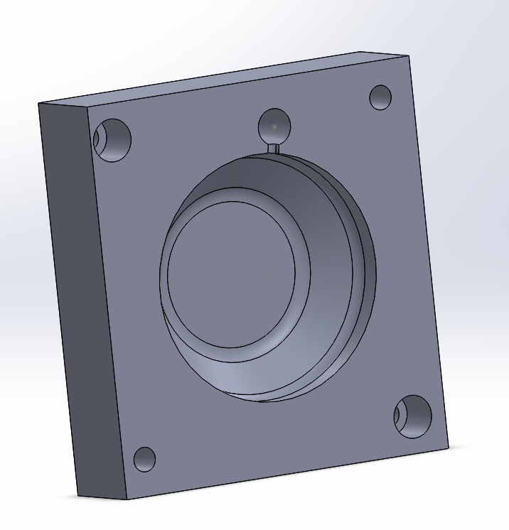
Body Cavity

Body Core

Bugs Bunny Cavity

Bugs Bunny Core

Although we made 5 different kinds for the molds, this blog will focus on the design considerations for the Bugs Bunny disk mold. In order to create this part, we decided to use injection molding. This meant that we had to create two blocks.

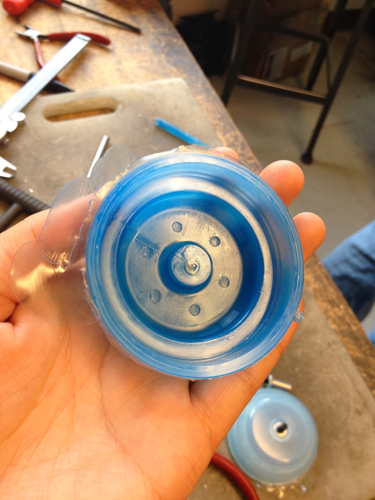
In order to modify the mold to account for the shrinkages, we found a part that was similar to the part that we were going to make.


For the green mushroom piece, the diameter of the piece was measured to be 2.179" and the diameter of the mold was measured to be 2.222". Dividing the difference in dimensions by the mold diameter, we calculated a 2% difference. The thickness of the piece was ~0.097" and the the depth of the mold was ~0.1". Again, this difference was calculated to be about 2%. This number agrees with the 1-3% shrinkage that was mentioned in the lecture. Therefore, we increased the dimensions by 2% in all the thickness and the disk diameter in order to compensate for shrinkage. All changes to the dimensions of the parts were made in Mastercam.

For the runner, we measured the runner size and depth from the Mario mold seen in lab. This part also had a thickness of around .1", so we thought it was a reasonable part to base our runner size off. The runner size was measured to be 0.125" wide and 0.030" deep.

For the Bugs Bunny mold, we decided to predominantly use the mill instead of the lathe. For the core mold, we could only make the geometry on the mill. The cavity mold on the other hand could be made on the lathe, but since we had to make a runner from the sprue hole, we figured it would be easier to just use the mill.

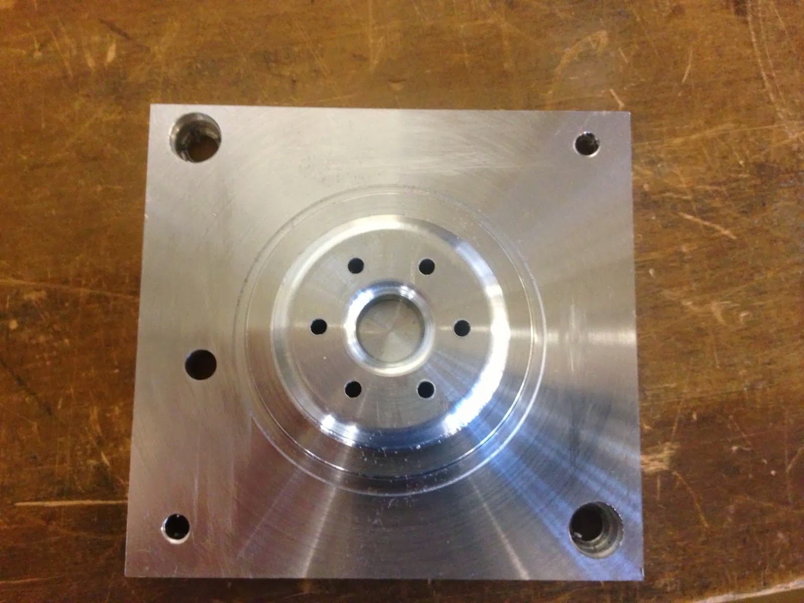
In order to manufacture the Bugs Bunny cavity, we planned on using the mill to face the mold, create the disk cavity, and machine the runner channel. To manufacture the Bugs Bunny core, we planned on facing the mold around the Bugs Bunny then reducing the tool size to get the detail on the Bugs Bunny design that we wanted. Once the Bugs Bunny shape was outlined, we would drill 10 ejector pin holes around the Bugs Bunny, but within the disk radius. 

After lab on Tuesday, we had to update process plan for the Bugs Bunny mold can be seen in our Process Plan.


While making our molds, we had to change a couple things. The first big thing was that we needed to face the top surfaces of our molds completely. Dave explained that the stock is not entirely flat, so facing would be useful. Our team also didn't realize that we offset by 0.01" when we set up the stock, so we had to change that for our molds. Therefore, we added a facing operation to the stock before we began. For the core mold, we only faced the area where Bugs Bunny was going to be in order to save time facing the mold.

Additionally, the feed rate on some of the facing operations for the 1/2" end mill was set to be pretty slow (3" per minute), likely because a smaller tool was originally used when the path was created. We ended up increasing the feed rate to 20" per minute, reducing our run time significantly.

The last change we had to make was modifying drilling of the holes on the core. The hole depths were originally not deep enough, so the center drill barely touched the surface of the mold. Therefore, the depth needed to be changed in Mastercam for the peck drill path. Additionally, the retraction of the drill bit was originally offset, which was potentially dangerous for our mold since the drill bit might have crashed into our part!

Once these changes were made, we set up the machines and let them run!
Joey, changing out the tools on the mill

Milling out the Bugs Bunny core

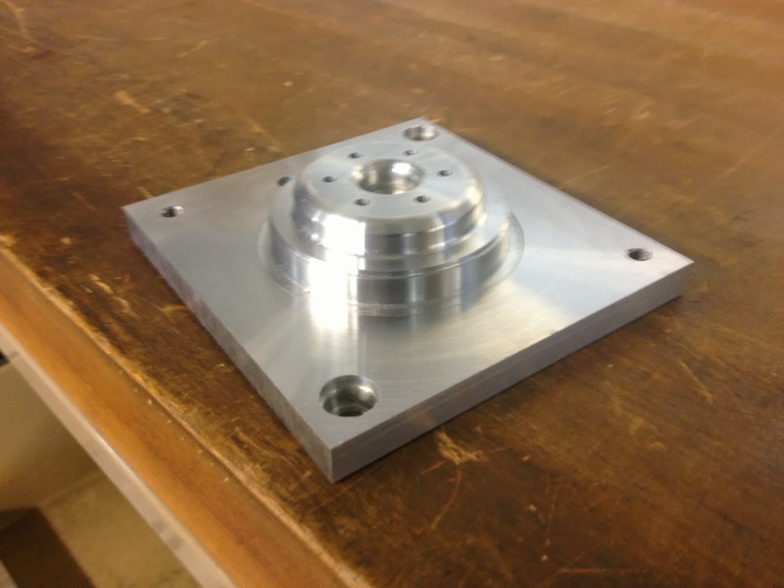
Our Bugs Bunny core mold before finishing

After the molds were made, they were cleaned up using a deburring tool and a file. The ejector pin holes were reamed out another 0.001" to allow for a slip fit for the ejector pins.

Our finished molds!


Tuesday, October 8, 2013

Lab Time Fun

Today, the group worked on double checking all the drawings and the Mastercam files.

At around 10:30, we started making our first mold for the orange cavity.
When we met with Dave to go over our tool paths, he suggested that we face the surface before we make the cavity for the mold. Additionally, we needed to change the direction of the chain. Oops!
We added this and updated the code on the dropbox.

Then we started making the mold! Yay.


Machining the mold!


First mold of the 2.008 season!! Almost done, minus the runner.


The only thing that we noticed was that there is a little bit of a dotted line along the inner edge of the cavity. 


Dave said this was because the tool we used for the finish was 5, which isn't as stiff of a tool. The divots were due to the tool vibrations as it was finishing that inner radius. He suggested using tool 10 for both the rough and finish cuts, but then we would have a larger radius on the inside of the tool.


Monday, October 7, 2013

Table of Specifications for Yoyo


To download our table of specifications, please visit this link!


Yoyo Project Management

In order to keep our team organized, we've utilized multiple different resources:

We created a Gantt Chart to help us keep track of deadlines:

A link to the chart can be found here.

Another resource that we've bee using extensively is a website called Trello.
It's a great website that allows us to delegate different tasks and break them down into different sections, which we find is easier to use than the Gantt chart.


In order to share files, we've been utilizing dropbox. Although it seemed like a good idea initially, it's been a little hard to keep track of versions and stuff between the computers. We think it would be better if we could download the dropbox application to the computers here and automatically save to a folder on our own computer... but we can't do this. Perhaps we should have used the 2.008 user accounts, but we're almost done with all our files anyways so changing at this point would not be worth it.

Lastly, to maintain documents and tables, we've been extensively using Google Docs. It's been working pretty well!

As far as the breakdown of the responsibilities for the project, each person on the team was assigned a part of the yoyo:
  • Rings: Sarah and Rohun (Injection Molding)
  • Bugs Bunny Insert: Kirsten and Joey (Injection Molding)
  • Body: David and Nathan (Injection Molding)
  • White disk and Basketball cover: Steven (Thermal Forming)
More specifically, by dividing these parts between these people, each of us was responsible for producing the Solidworks models for these parts, the Solidworks models for the molds, and developing the tool paths for creating these molds.

Additional responsibilities that we have are:
  • Gantt Master: Rohun
  • Blogger: Kirsten
  • Accountability Buddy: Nathan


Sunday, October 6, 2013

SpaceJam Yoyo Design


 As was seen in our last post, our yoyo design is finished. Both sides of the yoyo feature the same lovely design of Bugs Bunny in the Air Jordans logo, surrounded by the Looney Tunes rings.
A beautiful render of our yoyo

The general shape of our yoyo is a butterfly design, which we thought was a better design for a yoyo because it helps to guide the string into the groove and runs smoother. Also, you can do more tricks with a butterfly design.


Our yoyo design features 7 different parts:
  • Red Ring: Injection molded part, will snap inside the orange ring.
  • Orange Ring: Injection molded part, will snap inside the red body
  • Clear Basketball Cover: Thermal formed part, will sit flush inside the rings and with the top face of the body
  • Black Bugs Bunny Insert: Injection molded part, will sit underneath the basketball cover
  • White Disk Insert: Thermal formed plastic, die cut into a circle
  • Metal Ring: Stock steel metal ring, used to weight down the yoyo
  • Red Body: Injection molded part, will house all the other parts inside the yoyo
Once these parts are all manufactured, the injection molded parts will need to have the runners cut off, the thermal formed parts will need to be cut down using a die, and the strings will need to be cut down for the yoyos.

The assembly of the yoyo can be seen in this exploded view of the drawing.
The metal ring will be snapped inside the red body of the yoyo. The white disk insert and the Bugs Bunny insert will then be placed on top of the metal ring. The basketball cover will be placed on top of the Bugs Bunny insert, and then the two rings will be snapped in place on top of the cover. Once each half of the yoyo is assembled, the strings will need to be tied around the shafts and the two halves of the yoyos will need to be screwed together.

During the design of our components, we took into consideration the manufacturing process.

When we were designing the components, we made sure to not exceed the maximum volume of 2.70 in^3. We also made sure that the thickness of the body was more or less uniform thickness throughout the part to allow for a good finish of the plastic.

While designing the Bugs Bunny insert, we made sure to design the curve such that the smallest end mill would be able to be used to manufacture the mold for the part. The design was also made such that the center of mass would be approximately still in the center of the yoyo. Additionally, we made sure to make the Bugs Bunny insert 1/16" thick, to prevent warping of the plastic that occurs due to the large sections of the disk like we saw on some other yoyo parts.

Example of warping on plastic disks

For the fits on the plastic rings and parts that need to press fit into the yoyo, we made sure to follow the tolerances of +0.000"/-0.005"for ID features and +0.005"/-0.000" for OD features. We also tried to make sure that the length of engagement for the rings was about .150" deep.